1週目
注釈
以下の項目について、全員がすべてを試す必要はありません。役割分担をして、確認と理解をすすめてください。
電源の切り方・入れ方
- 電源を入れるには、電源ボタンを、2秒間長押しします。
- 電源を切るには、電源ボタン(M5と書かれたAボタンの左側面)を、6秒間長押しします。その際、プログラムによっては再スタートしたように見える場合がありますが、気にせずに長押し継続してください。
- 動画をみる→ https://youtu.be/Lo1jZbAeT8Y
- M5StickCガイド の、4ページ目、ハードウェアの概要も参考になります。
プログラムの書き込み方
プログラムの書き込み を参照してください。
コードを書くときのヒントと注意
- 以下のソースコード例は、右上のボタンを押すと、クリップボードに簡単にコピーできます。
- ソースコードのインデントは、CTRL+T (Macの場合はCommand+T)キーで、自動整形できます。
#include <M5StickC.h>は、M5StickC用のコードです。 M5StickCPlus では、#include <M5StickCPlus.h>に変更しないと、表示がおかしくなることがあります。- 大文字と小文字は厳密に区別されます。
- 画面をつかうプログラムを書き込んだあと、画面を使わないプログラムを書き込むと、前のプログラムの画面が残ることがあります。
- スケッチブック(プログラムを構成する、複数のソースコードを含むファイル、他のIDEではプロジェクトと呼ぶ場合もある)をコピーしたいときは、内包するフォルダごとコピーしてください。その際、フォルダ名と、メインのソースコードファイル名(拡張子以外の部分)は、一致している必要があります。
Serial通信
リスト 1 は、シリアルモニタへ文字列を出力するシンプルな例です。グローバル変数 num を 0 に設定したうえで、setup()関数が1回実行されます。その後、loop()関数が繰り返し実行されます。 プログラムの出力をみるには、Arduino IDEで「シリアルモニタ」をひらいてください。コードエディタ右上の虫眼鏡アイコンボタンをおします。 Serialクラスには、print()関数、println()関数、 printf()関数があります。Serial通信を用いると、デバイス側の変数の値や状況を、PC側で確認するプログラムを書くことができます。
1 2 3 4 5 6 7 8 9 | int num = 0;
void setup() {
Serial.begin(115200); // 通信速度をbpsで設定
}
void loop() {
Serial.printf("%d \n" , num);
num++;
delay(500); // 500ミリ秒待つ
}
|
シリアルモニタは、デバイスからの出力を確認するだけではなく、デバイスに文字を送信することもできます。リスト 2 は、シリアルモニタを介して、PCからデバイスに文字を送信する例です。シリアルモニタ上部のテキストエリアから 0 を送信すると、カウンタ num をリセットします。10〜14行目で、PCから送信された文字を、1文字ずつ Serial.read() で読み取って、配列 buf に格納しています。PCから複数の文字を1回で送信すると、 Serial.available() は連続して 1 (=true) を返しますので、1回に送信された文字をすべて buf に格納することができます。ちなみに、シリアルモニタで送信された文字列の最後は、改行コード(10)が付与されます。
1 2 3 4 5 6 7 8 9 10 11 12 13 14 15 16 17 18 19 20 21 22 23 24 25 26 27 28 29 | int num = 0;
char buf[100];
void setup() {
Serial.begin(115200); // 通信速度をbpsで設定
}
void loop() {
int pos = 0;
while (Serial.available()) { //PCから送信された文字があるあいだ、くりかえす
char c = Serial.read(); // 1バイト読み取る
buf[pos] = c; // 配列buf に格納
pos++; // 格納位置をひとつ右へ
}
if (pos > 0) {
buf[pos] = 0; // さいごに Null (文字列の終端)を追加(これを忘れるとどうなる?)
Serial.print("> from pc: ");
Serial.print( buf ); // 格納しておいた文字列を表示
if (buf[0] == '0' && pos == 2) { // buf={ 48(='0'), 10(=改行) } のとき
num = 0; // num を 0 にする
Serial.println( "Reset num" );
}
delay(2000);
}
Serial.printf("%d \n" , num );
num++;
delay(500);
}
|
注釈
16行目の処理を忘れると、どうなるでしょうか? また、buf が溢れると、なにが起きるでしょうか?プログラムを書くときは、常に例外的な事象がおきる可能性を考えておきましょう。ただし、全ての例外的な事象に対処するのは困難な場合が多いです。
本体の液晶ディスプレイ(LCD)
- M5StickCのDisplay周り解析 <https://lang-ship.com/blog/work/m5stickc-display> が詳しいです。
- リスト 3 のサンプルでは、外側から内側に向かって、10ピクセルずつ余白を残しながら、色を変えて塗りつぶしています。その後、8,16,26ピクセルフォント(それぞれ1,2,4番)をsetCursor()関数で指定して、print()関数で文字列を描画しています。
- M5StickCPlusの機能である液晶ディスプレイ(LCD)を使用するため、
#include <M5StickCPlus.h>を指定し、M5.begin()を呼び出しています。
1 2 3 4 5 6 7 8 9 10 11 12 13 14 15 16 17 18 19 20 21 22 23 24 25 26 27 28 29 30 31 32 33 34 35 | #include <M5StickCPlus.h>
void setup() {
M5.begin();
M5.Lcd.setRotation(3);
M5.Lcd.fillRect(0, 0, 240, 135, RED);
//M5StickCPlusの画面サイズは、240 x 135
M5.Lcd.fillRect(10, 10, 220, 115, ORANGE);
M5.Lcd.fillRect(20, 20, 200, 95, YELLOW);
M5.Lcd.fillRect(30, 30, 180, 75, GREENYELLOW);
M5.Lcd.fillRect(40, 40, 160, 55, CYAN);
M5.Lcd.fillRect(50, 50, 140, 35, BLUE);
M5.Lcd.fillRect(60, 60, 120, 15, MAGENTA);
M5.Lcd.setTextFont(1); // 8pixel ASCII font
M5.Lcd.setTextSize(1); // Magnify (x1-7)
M5.Lcd.setTextColor(WHITE);
M5.Lcd.setCursor(10,1); M5.Lcd.print("RED");
M5.Lcd.setTextColor(BLACK);
M5.Lcd.setCursor(20,11); M5.Lcd.print("ORANGE");
M5.Lcd.setCursor(30,21); M5.Lcd.print("YELLOW");
M5.Lcd.setCursor(40,31); M5.Lcd.print("GREENYELLOW");
M5.Lcd.setCursor(50,41); M5.Lcd.print("CYAN");
M5.Lcd.setTextColor(WHITE);
M5.Lcd.setCursor(60,51); M5.Lcd.print("BLUE");
M5.Lcd.setCursor(70,60,2); M5.Lcd.print("MAGENTA (2)");
// setCursorの第3引数は、TextFont番号
M5.Lcd.setTextColor(BLACK);
M5.Lcd.setCursor(30,90,4); M5.Lcd.print("26pixel ASCII (4)");
}
void loop() {
}
|
画面の向きは、setRotation() 関数で、設定します。0〜3までの整数で、指定します。
注釈
フォントの種類を設定するときは、setTextFont() や、setCursor()の第3引数をつかいます。setTextSize()は、指定したフォントを何倍に引き伸ばして表示するか?なので、基本は1を指定することが多いです。倍率を増やすと、ギザギザが目立ちます。
本体のボタン
本体には、3つのボタンがあります。 (参考:M5StickCガイド の、4ページ目、ハードウェアの概要)
リスト 4 に、ボタンをおしたらシリアルモニタに表示する例を示します。ボタンも、M5StickC/CPlusの機能なので、 #include <M5StickCPlus.h> を指定し、M5.begin() を呼び出しておく必要があります。また、ボタンの状態を読み出して、ボタンオブジェクト(BtnA,BtnB)に設定するために、 M5.update() を、ループのなかに入れておく必要があります( update()の定義 )。長押しと普通押しを区別したい場合は、ifで確認する順番(長押しを先に判定する)が重要です。
1 2 3 4 5 6 7 8 9 10 11 12 13 14 15 16 17 18 19 20 21 22 23 | #include <M5StickCPlus.h>
void setup() {
M5.begin();
M5.Lcd.setRotation(3);
}
void loop() {
M5.update(); // 各ボタンの状態を(読み取って)更新する:ボタンを判定するときは必須。
if (M5.BtnA.wasReleasefor(1000) ) {
Serial.println("[A] was Pressed longer than 1s");
} else if (M5.BtnA.wasReleased()) {
Serial.println("[A] was Pressed");
} else if (M5.BtnB.wasReleasefor(1000) ) {
Serial.println("[B] was Pressed longer than 1s");
} else if (M5.BtnB.wasReleased()) {
Serial.println("[B] was Pressed");
} else if (M5.Axp.GetBtnPress() == 2) {
Serial.println("[Power] was Pressed");
}
delay(10);
}
|
注釈
非公式リファレンスの「ボタン管理(Button)」 も参考になります。
文字列の扱い、16進数や10進数の変換
リスト 5 に、文字列から整数に変換したり、16進数表現の文字列を10進数に変換する例を示します。
Stringクラスを用いると、char配列 / byte配列 / 小文字変換や、空白改行の削除(ただし文字列の前後のみ)、部分文字列の取得などができます。
元のデータが保持されるメソッドと、破壊されるメソッドがあることに注意しましょう。
M5系デバイスのLCDでは、色を16ビット値(赤5bit/緑6bit/青5bit)で表現しています。 M5.Lcd.color565() という関数もありますが、ここではビット演算の理解を深めるため、関数を定義しています。
C言語のポインタや、シフト演算などを理解していると、このような処理を円滑に記述できるようになります。
1 2 3 4 5 6 7 8 9 10 11 12 13 14 15 16 17 18 19 20 21 22 23 24 25 26 27 28 29 30 31 32 33 34 35 36 37 38 39 40 41 42 43 44 45 46 47 48 49 50 51 52 53 54 55 56 57 58 59 60 61 62 63 64 65 66 67 68 69 | #include <M5StickCPlus.h>
void setup() {
Serial.begin(115200);
M5.begin();
M5.Lcd.setRotation(3);
Serial.println("整数 または 6文字の16進数(RRGGBB)を入力してください。");
}
String str = ""; // String: 可変長の文字列クラス
void loop() {
char buf[100] = {0};
int pos = 0;
while (Serial.available()) { //PCから送信された文字があるあいだ、くりかえす
char c = Serial.read(); // 1バイト読み取る
buf[pos] = c; // 配列buf に格納
pos++; // 格納位置をひとつ右へ
}
if (pos > 0) {
buf[pos] = 0;
String sbuf = buf;
sbuf.trim(); //文字列の前と後の空白と改行を取り除く(破壊的メソッド)
str.concat(sbuf); // 文字列の連結 (意味としては、str = str + sbuf)
Serial.println(str);
if (isDigit(sbuf)) {
int num = sbuf.toInt();
Serial.println( num * num );
}
if (sbuf.length() == 6) { // RRGGBBとして、LCD画面の背景を塗りつぶす
sbuf.toLowerCase();
uint8_t r = hexToDec( sbuf.substring(0, 2) );
uint8_t g = hexToDec( sbuf.substring(2, 4) );
uint8_t b = hexToDec( sbuf.substring(4, 6) );
M5.Lcd.fillScreen( getColorUInt16( r , g , b ) );
M5.Lcd.setCursor(0, 70, 4);
M5.Lcd.printf(" %02x %02x %02x \n", r, g, b);
M5.Lcd.printf(" %d %d %d ", r, g, b);
}
}
delay(50);
}
//全ての文字が0〜9なら、1(true)を返す
bool isDigit(String s) {
bool isAllDigit = true;
const char *p = s.c_str(); // String.c_str() は、NULLで終端されたchar配列の先頭アドレスを返す
while ( *p != 0 ) {
if (*p < '0' || '9' < *p) isAllDigit = false;
p++;
}
return isAllDigit;
}
// M5 用の、16ビットカラー値に変換 引用:https://qiita.com/nnn112358/items/ea6b5e81623ba690343c
uint16_t getColorUInt16(uint8_t red, uint8_t green, uint8_t blue) {
return ((red >> 3) << 11) | ((green >> 2) << 5) | (blue >> 3);
}
// 引数hex が16進表記の文字列だと仮定して、10進の値を返す
uint8_t hexToDec(String hex) {
int dec = 0;
int tmp = 0;
for (int p = 0; p < hex.length(); p++) {
tmp = int(hex.charAt(p));
if ( '0' <= tmp && tmp <= '9' ) tmp = tmp - '0';
if ( 'a' <= tmp && tmp <= 'f' ) tmp = tmp - 'a' + 10;
if ( 'A' <= tmp && tmp <= 'F' ) tmp = tmp - 'A' + 10;
tmp = constrain(tmp, 0, 15); //例外処理
dec = (dec * 16) + tmp;
}
return dec;
}
|
注釈
変数の型一覧 uint16_t は unsigned int 16bit type の略です。
参考:M5StackのLCDディスプレイの色をRGBで指定する。
ブザー(Beep)
リスト 6 は、内蔵Beepを鳴らすサンプルです。音の周波数は、最初の1オクターブ (f[0]〜f[6]) のみを配列宣言時に指定し、残りの3オクターブはsetup()内で、倍数を計算して配列に設定しています。
setBeep() と beep() を使うと、同じビープ音を使い回すときは記述が短くて便利ですが、通常は tone() のほうが簡潔です。
どちらの記法でも、命令実行のあと、音の停止を待たずに、すぐに次の処理に移行します(ノンブロッキング)。
継続ミリ秒数(ms)は、 M5.Beep.update() が周期的に呼び出せるときに指定し、それ以外は省略するとよいでしょう。(結局、 delay() と mute() が必要になるため)
1 2 3 4 5 6 7 8 9 10 11 12 13 14 15 16 17 18 19 20 21 22 23 24 25 26 27 28 29 30 31 32 33 34 | #include <M5StickCPlus.h>
int f[28] = { 262, 294, 330, 349, 392, 440, 494 }; // 配列のサイズは4オクターブ分
void setup() {
Serial.begin(115200);
M5.begin();
M5.Lcd.setRotation(3);
for (int i = 0; i < 7; i++) {
f[i + 7] = f[i] * 2;
f[i + 14] = f[i] * 4;
f[i + 21] = f[i] * 8;
}
// setBeep( Hz, ms) でビープ音を設定して、beep()で鳴らす。
M5.Beep.setBeep(523, 500); M5.Beep.beep(); delay(500);
// tone( Hz, ms ) で鳴らす方法
M5.Beep.tone(1046, 500); delay(500);
// msを省略し、tone( Hz ) で鳴らす(結局、delayが必要になるので)
M5.Beep.tone(2092); delay(500);
// ここはmsを指定するとよい (loopのM5.Beep.updateが停めてくれるので、delayを省略できる)
M5.Beep.tone(2092 * 2, 1000);
}
void loop() {
M5.Beep.update(); //tone()やsetBeep()で指定した時間を過ぎていたら音を止める。
// M5.Beep.mute() とすると、すぐに停止する。
while (Serial.available()) {
char c = Serial.read();
if (c < 'c' || 'z' < c) continue; // c〜zの文字以外なら、以降のwhile内処理をスキップ
M5.Beep.tone( f[c - 'c'] , 1000); // 1秒鳴らす
Serial.println( f[c - 'c'] );
}
delay(50);
}
|
内蔵LED(赤・赤外)
M5StickCPlusには、2つのLEDランプが内蔵されています。GPIO(General Purpose I/O)10 には、赤色LED、GPIO9 には、赤外LEDが接続されています。 場所は、USBケーブルを挿す面の反対側の面にある、小さな穴2つの内側です。
リスト 7 は、赤色LEDを点滅させるシンプルなプログラムです。
1 2 3 4 5 6 7 8 9 10 11 12 13 14 15 | int PIN = 10; // 赤色LED G10
//int PIN = 9; // Ir LED (カメラには映りますが、肉眼では見えません) G9
// その他、G0 (0) , G25 (25), G26 (26) がつかえます。
// https://lang-ship.com/blog/work/m5stickc-io/
void setup() {
pinMode(PIN, OUTPUT); // PINのモード設定
}
void loop() {
digitalWrite(PIN, HIGH); // HIGH = 1
delay(1000);
digitalWrite(PIN, LOW); // LOW = 0
delay(500);
}
|
外部のLED等を接続
外部のLED等は、 G0, G25, G26 に接続します。(GROVE端子のG32, G33も利用できます。) サンプルプログラムは、リスト 7 と同様です。PIN 番号を、0 / 25 / 26 に変更してください。
ブレッドボードに、抵抗とLEDを直列に接続します。 LEDの長い足のほうに、G0 (or G25 or G26) をジャンパワイヤで接続し、反対側(短い足)のほうを、GND (グランド)に接続します。 ポートを「HIGH」にすると、3.3Vの電圧がかかります。
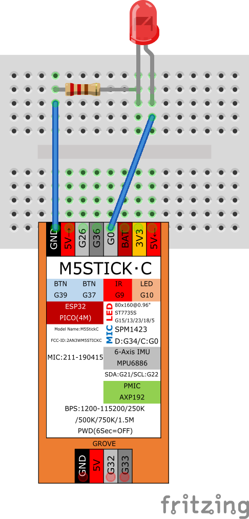
警告
LEDのみで回路を構成しないよう注意!一般に、LEDは抵抗をつないで使用しないと、故障したり、最悪の場合破裂したりして危険です。ただし、抵抗入りLEDであれば問題ありません。
PWM (Pulse Width Modulation)
パルス幅変調とは、信号の周期Tに対する、パルスの幅を変化させる方法です。 直流モータの速度制御や、サーボモータの制御、LEDの明度調整などに使われます。
リスト 8 は、赤色LEDを点滅させるシンプルなプログラムです。 ledcSetup(チャンネル, 周波数, 分解能) で、PWMチャンネル(0〜3)に対する周波数と分解能設定をし、 lecAttachPin(ピン番号, チャンネル) で、PWMチャンネルを適用する出力ピンを選択します。そのあと、 ledcWrite(チャンネル, 値) で、分解能で設定したビットで表現できる最大値+1以下の値を指定することで、デューティー比を設定します。リスト 8 の場合、分解能で8bitを指定したので、0〜256 の値が、デューティー比 0〜1 のパルス生成に対応します。
1 2 3 4 5 6 7 8 9 10 11 12 13 14 15 16 17 18 19 20 21 22 | int PIN = 10; // 内蔵LED
int PWM_CH = 1; // 0~3で指定する。0にすると高音が鳴って耳障り?
void setup() {
pinMode(PIN, OUTPUT); // PINのモード設定
ledcSetup(PWM_CH, 90, 8); // CH, 周波数(Hz) 【小さくするとどうなる?】, 分解能(bit)
ledcAttachPin(PIN, PWM_CH);
// https://lang-ship.com/reference/unofficial/M5StickC/Peripherals/LED_Control/
}
void loop() {
int i;
for (int i = 0 ; i < 256 ; i++) {
ledcWrite(PWM_CH, i);
delay( 5 );
}
for (int i = 256 ; i > 0 ; i--) {
ledcWrite(PWM_CH, i);
delay( 5 );
}
}
|
注釈
ソースコードのコメントにも書いていますが、周波数を小さくする(20〜30程度)と、どうなるでしょうか?ぜひやってみてください。
サーボモータ(サーボハット利用)
リスト 9 は、サーボハット のサーボモータを動かすサンプルです。サーボモータの制御はPWMですので、基本的に、上のPWMとやっていることは同じです。おまけとして、LEDも点灯させました。map関数 は、Arduinoで使える関数で、範囲に対応する値を変換するときに使います。ここでは、サーボ制御で用いる5〜33の値を、LED制御の値0〜256に変換しています。
1 2 3 4 5 6 7 8 9 10 11 12 13 14 15 16 17 18 19 20 21 22 23 24 25 26 27 28 | #define MLOW 5
#define MHIGH 33
void setup() {
ledcSetup(1, 50, 8); //サーボハット CH1
ledcAttachPin(26, 1);
pinMode(10, OUTPUT);
ledcSetup(2, 100, 8);//LED CH2
ledcAttachPin(10, 2);
}
void loop() {
for (int i = MLOW; i <= MHIGH; i = i + 1) {
ledcWrite(1, i);
int v = map(i, MLOW, MHIGH, 0, 256); // 範囲5〜33に対するiの値を、範囲0〜256に変換
ledcWrite(2, v);
delay(50);
}
delay(300);
for (int i = MHIGH; i >= MLOW; i = i - 1) {
ledcWrite(1, i);
int v = map(i, MLOW, MHIGH, 0, 256);
ledcWrite(2, v);
delay(20);
}
delay(300);
}
|
アナログセンサを接続 (ADC)
ADCは、Analog to Digital Converter の意味です。
analogRead(PIN) は、PIN番ピンの電圧(0~3.3V)を、0〜4095 の値で返します。一般に、抵抗値が変化するタイプのセンサは、この方法をつかって、読み取ることができます。
警告
ADC にかいてあるように、G26, G32, G33, G36のみ使えます。G26は、無線利用時には使えません。
リスト 10 はCdSセル(照度センサ) の値を読み取るサンプルです。
1 2 3 4 5 6 7 8 9 10 11 12 13 14 15 16 17 18 19 | int PIN = 26;
// +--- 15kΩ抵抗 --+-- CdSセル --+
// | | |
// GND G26 3V3
// https://www.storange.jp/2012/03/arduinocds.html
// 注意点: https://lang-ship.com/reference/unofficial/M5StickC/Peripherals/ADC/
void setup() {
Serial.begin(115200);
pinMode(PIN, ANALOG); // PINのモード設定
// https://lang-ship.com/blog/work/m5stickc-io/
}
void loop() {
Serial.printf("%04d\n", analogRead(PIN) ); // 暗 0 〜 4095 明
delay(1000);
}
|
圧力センサや、曲げセンサも、同様の方法で利用することができます。
加速度センサ
リスト 11 は、内蔵されている加速度センサ(MPU6886) の値を表示するサンプルです。ちなみに、IMUとは、Inertial Measurement Unit: 慣性計測装置 の略です。 「ツール」→「シリアルプロッタ」をひらくと、値をグラフでみることができます。 ジャイロセンサの値も取得可能です。
1 2 3 4 5 6 7 8 9 10 11 12 13 14 15 16 17 18 19 20 21 22 23 24 25 26 27 | // 参考にしたサイト: https://qiita.com/kitazaki/items/1ce671532270cd44fabf
#include <M5StickCPlus.h>
float gyroX, gyroY, gyroZ; // ジャイロデータ
float ax, ay, az; // 加速度データ
void setup() {
M5.begin();
M5.Lcd.setRotation(3);
M5.IMU.Init();
Serial.begin(115200);
Serial.println("");
}
void loop() {
M5.IMU.getGyroData(&gyroX, &gyroY, &gyroZ);
M5.IMU.getAccelData(&ax, &ay, &az);
M5.Lcd.setCursor(0, 10, 2);
M5.Lcd.printf("aX :%7.2f \naY :%7.2f \naZ :%7.2f mg \n\n", ax , ay , az );
Serial.printf("%7.2f , %7.2f , %7.2f \n", ax , ay , az); //シリアルプロッタ用の出力
M5.Lcd.printf("gX :%7.2f \ngY :%7.2f \ngZ :%7.2f mg ", gyroX * M5.IMU.gRes, gyroY * M5.IMU.gRes, gyroZ * M5.IMU.gRes);
// Serial.printf("%7.2f,%7.2f,%7.2f,", gyroX * M5.IMU.gRes, gyroY * M5.IMU.gRes, gyroZ * M5.IMU.gRes);
delay(50);
}
|
赤外(InfraRed)リモコン
信号の読み取り
赤外線リモコン受信モジュールが必要です。ここでは、GP1UXC41QS を前提に、話をすすめます。
また、準備として、ライブラリマネージャにて、IRremoteESP8266 をインストールします。ちなみに、テストしたバージョンは2.7.15でした。
注釈
ライブラリマネージャは、「スケッチ」→「ライブラリをインクルード」→「ライブラリを管理…」で、ひらきます。
ファイルメニュー → スケッチ例 → IRremoteESP8266 → IRrecvDumpV2 を選択します。
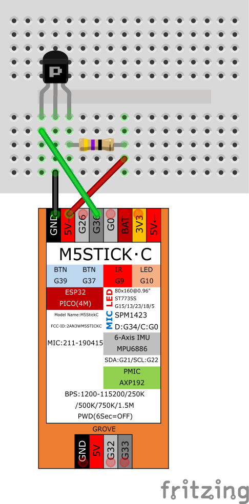
ブレッドボードに、以下の図のように配線します。Pとかいてある面が、受光器が出っ張っている面だとおもってください。47Ωの抵抗を、5Vとの間に入れます。
赤外線リモコン受信モジュールに接続したピンを const uint16_t kRecvPin = 36; として設定します。
受光器にリモコンを向けて、ボタンを押すと、シリアルモニタに情報が表示されます。ここでは、Protocol : NEC , Code 0x2FD48B7 (32 Bits) と表示されたとします。この数値(uint32_t)を覚えておきます。
信号の送信
内蔵の赤外LEDを用いて、信号を送信する例を リスト 12 に示します。 内蔵の赤外LED光はあまり強くないため、50cm程度まで近づかないと反応しない場合があります。 単体の赤外LEDを接続して用いると、距離を伸ばすことができます。
なお、NECフォーマットではない赤外線リモコンの通信フォーマットについては、 赤外線リモコンの通信フォーマット や、スケッチ例を参考にしてください。
1 2 3 4 5 6 7 8 9 10 11 12 13 14 15 | #include <IRremoteESP8266.h>
#include <IRsend.h>
uint16_t kIrLed = 9; // 内蔵IrLED
IRsend irsend(kIrLed);
uint32_t code = 0x2FD48B7; // Toshiba TV Power
void setup() {
irsend.begin();
}
void loop() {
irsend.sendNEC( code , 32);
delay(5000);
}
|
スプライト表示(TFT_eSprite クラス)
M5.Lcd ではじまる画面描画命令は、表示されている画面に対して、直接描画するため、画面のちらつきが生じることがあります。 TFT_eSprite クラスを用いると、画面に表示されていない仮想画面(オフスクリーン)を作成して、そこに対して描画を行っておき、さいごにまとめて仮想画面の内容をメインの画面(Lcd)に描画することができます。 これにより、画面のちらつきが抑制できます(ダブルバッファリング)。 ちらつき防止のほかに、なめらかに画面スクロールする目的で、実画面よりも大きい仮想画面を作成しておき、その一部の領域のみを実画面に描画するといった用途にも使われます。
TFT_eSprite クラスは、Lcdクラスとほぼ同様の描画関数を備えています。リスト 13 は、スプライトの効果あり/なしを確認できるサンプルプログラムです。
1 2 3 4 5 6 7 8 9 10 11 12 13 14 15 16 17 18 19 20 21 22 23 24 25 26 27 28 29 30 31 32 33 34 35 36 37 38 39 | #include <M5StickCPlus.h>
int USE_SPRITE = 0 ; //スプライトを使用するとき1
TFT_eSprite spu = TFT_eSprite(&M5.Lcd); // Sprite object
void setup() {
M5.begin();
M5.Lcd.setRotation(3);
spu.setColorDepth(8);
spu.createSprite(240, 135);
randomSeed(analogRead(0));
}
void loop() {
int r = random(100000);
if ( USE_SPRITE ) {
spu.fillSprite( CYAN );
spu.setCursor(30, 34, 4); spu.setTextSize(2);
spu.setTextColor( WHITE, BLUE );
spu.printf(" %d \n Sprite ", r );
spu.pushSprite(0, 0);
} else {
M5.Lcd.fillScreen( CYAN );
M5.Lcd.setCursor(30, 34, 4); M5.Lcd.setTextSize(2);
M5.Lcd.setTextColor( WHITE, BLUE );
M5.Lcd.printf(" %d \n LCD ", r);
}
M5.update();
if (M5.BtnA.wasReleased()) {
USE_SPRITE = 1 - USE_SPRITE ; // スプライト使用の切り替え(1なら0、0なら1)
M5.Beep.tone(1000 + 1000 * USE_SPRITE, 500);
}
M5.Beep.update();
delay(100);
}
|
Wifi 接続
リスト 14 は、Wifi接続のサンプルです。ssid と password には、環境にあわせたものを入力してください。接続すると、m5デバイスのIPアドレスを画面に表示します。本当にWifi接続できたかどうかを、PCのターミナルからpingを打つなどして、確認してみましょう。(Windowsの場合、コマンドプロンプトをひらき、ping のあとに、半角スペースと、確認したいIPアドレスを入れます)
1 2 3 4 5 6 7 8 9 10 11 12 13 14 15 16 17 18 19 20 21 22 23 24 25 26 27 28 29 30 31 32 | #include <M5StickCPlus.h>
#include <WiFi.h>
const char* ssid = "**********";
const char* password = "**********";
void setup() {
M5.begin();
M5.Lcd.setRotation(3);
M5.Lcd.fillScreen(ORANGE);
M5.Lcd.setCursor(10, 50, 4);
WiFi.begin(ssid, password); // 接続開始
while (WiFi.status() != WL_CONNECTED) { // 接続中...
M5.Beep.tone(2000); delay(200);
M5.Beep.mute(); delay(300);
M5.Lcd.print(".");
}
// 接続完了!!
M5.Beep.tone(4000);
M5.Lcd.fillScreen(GREEN);
M5.Lcd.setCursor(0, 40, 4);
M5.Lcd.setTextColor(BLACK, GREEN);
M5.Lcd.print(" Wifi Connected!\n ");
String gotip = WiFi.localIP().toString(); // m5デバイスのIPアドレス
M5.Lcd.println(gotip);
delay(1500);
M5.Beep.mute();
}
void loop() {
}
|
Wifi接続するだけでは、あまり意味がないので、Telnetサーバを起動する例を リスト 15 に示します。
シリアルモニタを開いて、IPアドレスを確認したら、ターミナル(コマンドプロンプト)で、telnet IPaddr と入力して、接続します。
telnet から文字を入力すると、シリアルモニタに表示されます。
逆に、シリアルモニタから文字を入力すると、Telnet接続しているターミナルに、文字が表示されます。
WiFiServer server(23) で、23番ポートで待ち受けるサーバを、作成しています。
ちなみに、WiFiMulti は、複数のアクセスポイントに対して、Wifi接続を試みることができる機能(クラス)です。ただし、最終的に繋がるのは1つのアクセスポイントになります。
注釈
Telnet接続を切断するときは、まずControlキーをおしながら ] をおしてください。プロンプトが telnet> と表示されますので、quit と打ち込むと終了します。 Escape character is '^]'. の ^ は、Controlキーのことです。
1 2 3 4 5 6 7 8 9 10 11 12 13 14 15 16 17 18 19 20 21 22 23 24 25 26 27 28 29 30 31 32 33 34 35 36 37 38 39 40 41 42 43 44 45 46 47 48 49 50 51 52 53 54 55 56 57 58 59 60 61 62 63 64 65 66 67 68 69 70 71 72 73 74 75 76 77 78 79 80 81 82 83 84 85 86 87 88 89 90 91 92 93 94 95 96 97 98 99 100 101 102 103 104 105 106 107 108 109 110 111 112 113 114 115 116 117 118 119 120 121 122 123 124 125 126 127 128 129 130 | // オリジナルのWifiTelnetToSerial を、改変しました。
/*
WiFiTelnetToSerial - Example Transparent UART to Telnet Server for ESP32
Copyright (c) 2017 Hristo Gochkov. All rights reserved.
This file is part of the ESP32 WiFi library for Arduino environment.
This library is free software; you can redistribute it and/or
modify it under the terms of the GNU Lesser General Public
License as published by the Free Software Foundation; either
version 2.1 of the License, or (at your option) any later version.
This library is distributed in the hope that it will be useful,
but WITHOUT ANY WARRANTY; without even the implied warranty of
MERCHANTABILITY or FITNESS FOR A PARTICULAR PURPOSE. See the GNU
Lesser General Public License for more details.
You should have received a copy of the GNU Lesser General Public
License along with this library; if not, write to the Free Software
Foundation, Inc., 51 Franklin St, Fifth Floor, Boston, MA 02110-1301 USA
*/
#include <WiFi.h>
#include <WiFiMulti.h>
WiFiMulti wifiMulti;
//how many clients should be able to telnet to this ESP32
#define MAX_SRV_CLIENTS 3
const char* ssid = "**********";
const char* password = "**********";
WiFiServer server(23);
WiFiClient serverClients[MAX_SRV_CLIENTS];
void setup() {
Serial.begin(115200);
Serial.println("\nConnecting");
wifiMulti.addAP(ssid, password);
// wifiMulti.addAP("ssid_from_AP_2", "your_password_for_AP_2");
// wifiMulti.addAP("ssid_from_AP_3", "your_password_for_AP_3");
Serial.println("Connecting Wifi ");
for (int loops = 10; loops > 0; loops--) {
if (wifiMulti.run() == WL_CONNECTED) {
Serial.println("");
Serial.print("WiFi connected ");
Serial.print("IP address: ");
Serial.println(WiFi.localIP());
break;
}
else {
Serial.println(loops);
delay(1000);
}
}
if (wifiMulti.run() != WL_CONNECTED) {
Serial.println("WiFi connect failed");
delay(1000);
ESP.restart();
}
//start UART and the server
// Serial2.begin(9600);
server.begin();
server.setNoDelay(true);
Serial.print("Ready! Use 'telnet ");
Serial.print(WiFi.localIP());
Serial.println(" 23' to connect");
}
void loop() {
uint8_t i;
if (wifiMulti.run() == WL_CONNECTED) {
//check if there are any new clients
if (server.hasClient()) {
for (i = 0; i < MAX_SRV_CLIENTS; i++) {
//find free/disconnected spot
if (!serverClients[i] || !serverClients[i].connected()) {
if (serverClients[i]) serverClients[i].stop();
serverClients[i] = server.available();
if (!serverClients[i]) Serial.println("available broken");
Serial.print("New client: ");
Serial.print(i); Serial.print(' ');
Serial.println(serverClients[i].remoteIP());
break;
}
}
if (i >= MAX_SRV_CLIENTS) {
//no free/disconnected spot so reject
server.available().stop();
}
}
//check clients for data
for (i = 0; i < MAX_SRV_CLIENTS; i++) {
if (serverClients[i] && serverClients[i].connected()) {
if (serverClients[i].available()) {
//get data from the telnet client and push it to the UART
while (serverClients[i].available()) Serial.write(serverClients[i].read());
}
}
else {
if (serverClients[i]) {
serverClients[i].stop();
}
}
}
//check ==UART== => Serial for data
if (Serial.available()) {
size_t len = Serial.available();
uint8_t sbuf[len];
Serial.readBytes(sbuf, len);
//push UART data to all connected telnet clients
for (i = 0; i < MAX_SRV_CLIENTS; i++) {
if (serverClients[i] && serverClients[i].connected()) {
serverClients[i].write(sbuf, len);
delay(1);
}
}
}
}
else {
Serial.println("WiFi not connected!");
for (i = 0; i < MAX_SRV_CLIENTS; i++) {
if (serverClients[i]) serverClients[i].stop();
}
delay(1000);
}
}
|
NTPサーバ (Network Time Protocol) と時刻の取得
M5StickCPlusには、システム時間(localTime)と、RTC(リアルタイムクロック:時計の機能を備えたICのこと)の2種類の時計があります。システム時間は、システムリセット(再起動)のたびに、時刻もリセットされますが、後者のRTCはリセットされません。
リスト 16 に、NTPサーバを使ってシステム時間の修正をしたのち、システム時間を1秒ごとに取得して、シリアルモニタに表示する例を示します。こちらは、M5のライブラリは不要です。configTime()でNTPサーバを設定しておくと、1時間に1回、NTPサーバに接続して、時刻修正します。
1 2 3 4 5 6 7 8 9 10 11 12 13 14 15 16 17 18 19 20 21 22 23 24 25 26 27 28 29 30 | #include <WiFi.h>
const char* ssid = "**********";
const char* password = "**********";
void setup() {
Serial.begin(115200);
WiFi.begin(ssid, password);
while (WiFi.status() != WL_CONNECTED) { // 接続中...
Serial.print(".");
}
char* ntpserver = "10.64.7.184"; // 学外なら、たとえば "ntp.nict.jp"
configTime(9 * 3600, 0, ntpserver);//GMTとの時差(秒), サマータイムで進める時間(秒)
}
void loop() {
struct tm localTime;
char buf[30];
getLocalTime(&localTime);
sprintf(buf, ">> %04d/%02d/%02d %02d:%02d:%02d",
localTime.tm_year + 1900,
localTime.tm_mon + 1,
localTime.tm_mday,
localTime.tm_hour,
localTime.tm_min,
localTime.tm_sec
);
Serial.println(buf);
delay(1000);
}
|
警告
configTime() を行わない状況で、システム時間(localTime)を取得しようとすると、取得に数秒ほど時間がかかります。
リスト 17 は、RTCの時刻を表示するサンプルです。なお、5行目で USE_NTP に 1 が設定してあれば、RTCに時刻を設定します。常時Wifiネットワークに接続できない場合は、RTCを利用することが望ましいです。
1 2 3 4 5 6 7 8 9 10 11 12 13 14 15 16 17 18 19 20 21 22 23 24 25 26 27 28 29 30 31 32 33 34 35 36 37 38 39 40 41 42 43 44 45 46 47 48 49 50 51 52 53 54 55 56 57 58 59 60 61 62 63 64 | #include <M5StickCPlus.h>
#include <WiFi.h>
// #include "time.h"
#define USE_NTP 0 // NTPからRTCに時刻設定するなら1
void setRTCfromLT(struct tm lt) {
RTC_DateTypeDef DateStruct;
DateStruct.Year = lt.tm_year + 1900;
DateStruct.Month = lt.tm_mon + 1;
DateStruct.Date = lt.tm_mday;
DateStruct.WeekDay = lt.tm_wday;
M5.Rtc.SetData(&DateStruct);
RTC_TimeTypeDef TimeStruct;
TimeStruct.Hours = lt.tm_hour;
TimeStruct.Minutes = lt.tm_min;
TimeStruct.Seconds = lt.tm_sec+1;
M5.Rtc.SetTime(&TimeStruct);
}
void getRTC(char* buf) {
RTC_DateTypeDef DateStruct;
RTC_TimeTypeDef TimeStruct;
M5.Rtc.GetData(&DateStruct);
M5.Rtc.GetTime(&TimeStruct);
sprintf(buf, "%04d/%02d/%02d %02d:%02d:%02d",
DateStruct.Year, DateStruct.Month, DateStruct.Date,
TimeStruct.Hours, TimeStruct.Minutes, TimeStruct.Seconds
);
}
void setup() {
M5.begin();
M5.Lcd.setRotation(3);
Serial.begin(115200);
if (USE_NTP) {
const char* ssid = "**********";
const char* password = "**********";
const char* ntpserver = "10.64.7.184"; // "ntp.nict.jp"
WiFi.begin(ssid, password);
while (WiFi.status() != WL_CONNECTED) { // 接続中...
Serial.print(".");
}
configTime(9 * 3600, 0, ntpserver);
struct tm localTime;
while (localTime.tm_year < 80) {
getLocalTime(&localTime); delay(50);
}
setRTCfromLT(localTime);
}
}
void loop() {
char buf[30];
getRTC(buf); // bufに、日時文字列を書き込む
Serial.println(buf);
M5.Lcd.fillScreen(BLUE);
M5.Lcd.setCursor(0, 50, 4);
M5.Lcd.println(buf);
delay(1000);
}
|
注釈
RTCに一旦時刻を設定しておくと、初期状態で書き込まれているプログラムFactoryTest の「BMP8563 RTC Time」でも、その時刻が表示されるようになります。
WebClient
リスト 18 は、HTTP通信で天気予報Web APIに接続するサンプルです。HTTPClientクラスを用いると、ブラウザでURLを指定してWebページを開くように、WebサーバにGETメソッドやPOSTメソッドでリクエストを送信して、ステータスコードやレスポンスを取得することができます。このサンプルでは、シリアルコンソールに、天気予報をJSON形式で表示します。JSON(ジェイソン)とは、Javascriptのオブジェクトの形式でデータを表現する記法です。
1 2 3 4 5 6 7 8 9 10 11 12 13 14 15 16 17 18 19 20 21 22 23 24 25 26 27 28 29 30 31 32 33 | #include <WiFi.h>
#include <HTTPClient.h>
const char* ssid = "**********";
const char* password = "**********";
// 天気予報API https://weather.tsukumijima.net/ から、千葉の天気を取得
const char* weatherapi_url = "http://weather.tsukumijima.net/api/forecast/city/120010";
void setup() {
Serial.begin(115200);
WiFi.begin(ssid, password);
while (WiFi.status() != WL_CONNECTED) { // 接続中...
delay(50);
Serial.print(".");
}
delay(1000);
HTTPClient http;
http.begin(weatherapi_url); //HTTPでサーバに接続
int httpCode = http.GET();
if (httpCode > 0) {
Serial.println(httpCode);
if (httpCode == HTTP_CODE_OK) {
String payload = http.getString();
Serial.println(payload);
}
}
http.end();
}
void loop() {
}
|
警告
https (SSL) 通信をする場合は、スケッチ例→HTTPClient→BasicHttpsClient を参照して、WiFiClientSecure クラスを使用してください。
Google Spreadsheet にデータを送信する
HTTP通信で、サーバにデータを送信して格納したいとおもっても、適当なサーバを準備するのは手間がかかることがあります。
Google Apps Scriptを用いると、HTTP通信で Google Spreadsheet にデータを書き込んだり、読み取ったりするWebサービスを作成し、WebAPIとして公開することができます。
(Google Spreadsheetのメニューで) 拡張機能→Apps Script または、ツール→スクリプトエディタ で、リスト 19 を「コード.gs」に書き込みます。15行目で「シート1」の一番下の行に、配列array の要素を追加します。19行目のgetRange(1,3).getValue()は、スプレッドシートのC1(3列1行)の値を取得しています。ここに「=average(C2:C200)」のようにしておくと、データの平均値を取得することもできます。
作成した「コード.gs」について、「公開」→「ウェブアプリケーションとして導入...」で、Webアプリとして公開できます。(なお、「新しいエディタ」では表示が異なるため、できない可能性があります。)
作成できたかどうかをパソコンから確認するには、コマンドラインから、以下のように入力します(ただし、curlが必要です。val1=10 と val2=20 のあいだは&記号ですので、シェルでバックグラウンド処理されないように、URLをシングルクォートで囲っています)
curl -L 'https://script.google.com/macros/s/XxXxXxXxXx/exec?val1=10&val2=20'
1 2 3 4 5 6 7 8 9 10 11 12 13 14 15 16 17 18 19 20 21 | function doGet(e) {
var spreadsheet = SpreadsheetApp.getActiveSpreadsheet();
var sheet = spreadsheet.getSheetByName('シート1');
var now = new Date();
var array = [];
array.push(now);
for(var k in e['parameter']) {
array.push(k);
array.push(e['parameter'][k]);
}
var params = JSON.stringify(e);
array.push(params);
sheet.appendRow( array );
var lastRow = sheet.getLastRow();
var output = ContentService.createTextOutput(sheet.getRange(1,3).getValue()+" "+lastRow);
output.setMimeType(ContentService.MimeType.TEXT);
return output;
}
|
WebServer
すこし長いですが、リスト 20 は、80番ポートでHTTPでの通信を待ち受け(listenし)て、クライアントからの接続情報(ヘッダ情報)を返すWebサーバのシンプルな例です。クライアント(ブラウザ)からのリクエスト行のうち、 GET または POST ではじまる行があれば、変数 meth に格納します。つまり、変数 meth には、ブラウザで発行したリクエストのURLが含まれることになります。POSTメソッドで送信されていれば、リクエストボディに記述されたデータを変数 post に格納します。 クライアント(ブラウザ)に返す「レスポンス」は、 client.println() で送信します。最後に、client.stop() で、サーバ側から接続を切断します。
1 2 3 4 5 6 7 8 9 10 11 12 13 14 15 16 17 18 19 20 21 22 23 24 25 26 27 28 29 30 31 32 33 34 35 36 37 38 39 40 41 42 43 44 45 46 47 48 49 50 51 52 53 54 55 56 57 58 59 60 61 62 63 64 65 66 67 68 69 70 71 72 73 74 75 76 77 78 79 80 81 82 83 84 | #include <WiFi.h>
const char* ssid = "**********";
const char* password = "**********";
WiFiServer server(80);
void setup() {
Serial.begin(115200);
WiFi.begin(ssid, password);
while (WiFi.status() != WL_CONNECTED) { // 接続中...
delay(50);
Serial.print(".");
}
String ip = WiFi.localIP().toString(); // m5デバイスのIPアドレス
Serial.printf("\nopen http://%s\n\n", ip.c_str() );
server.begin(); // Webサーバを開始
}
void loop() {
WiFiClient client = server.available();
if (client) {
String req = "" ;
String tmp = "" , meth = "" ;
while (client.connected()) { // loop while the client's connected
if (client.available()) { // if there's bytes to read from the client,
char c = client.read(); // read a byte, then
req += c;
if (c == '\n') { // if the byte is a newline character
if (tmp.length() == 0) { // end of request, break while loop
break;
} else { //まだ継続
if (tmp.startsWith("GET ") || tmp.startsWith("POST ") ) {
meth = tmp;
}
tmp = "";
}
} else if (c != '\r') { // if you got anything else but a carriage return character,
tmp += c; // add it to the end of the currentLine
}
}
} // end of while
Serial.println(meth);
if ( meth.startsWith("GET /") ) {
client.println("HTTP/1.1 200 OK"); // header (with response code)
client.println("Content-Type:text/plain");
client.println(""); // HTTPでは、header と body の区切りは改行
client.println(meth);
client.println("-- request --");
client.println(req);
}
if ( meth.startsWith("POST ") ) {
String post = "";
char buf[257];
int n;
while ((n = client.available()) > 0) {
if (n < 256) {
client.readBytes(buf, n) ;
buf[n] = 0 ;
} else {
client.readBytes(buf, 256) ;
buf[256] = 0 ;
}
}
post += buf ;
client.println("HTTP/1.1 200 OK");
client.println("Content-Type:text/plain");
client.println(""); // HTTPでは、header と body の区切りは改行
client.println(meth);
client.println("-- request --");
client.println(req);
client.println("-- post data --");
client.println(post);
}
// close the connection:
client.stop();
Serial.println(" --- Client Disconnected.");
}
delay(100);
}
|
センサデータを返すだけなら問題ありませんが、クライアントからのデータを GET / POST で受信して処理する場合は、 key1=val1&key2=val2 のような文字列を要素に分解する必要がでてきます。あまり深入りしませんが、正規表現で文字列を照合・抽出する Regexp や、抽出した結果をハッシュ/辞書として保存する Dictionary ライブラリを導入すると、複雑なリクエストやデータを扱いやすくなるでしょう。
リスト 21 に、RGBの色指定文字列などのリクエスト文字列をパースして辞書に追加するプログラムの断片を示します。注意:このプログラムは、単体では動作しません
1 2 3 4 5 6 7 8 9 10 11 12 13 14 15 16 17 18 19 20 21 22 23 24 25 | #include <Regexp.h>
#include <Dictionary.h>
Dictionary *dict = new Dictionary(); // 辞書/ハッシュ。キー文字列→値 を保持するデータ構造
void match_callback (const char * match, // matching string (not null-terminated)
const unsigned int length, // length of matching string
const MatchState & ms) // MatchState in use (to get captures)
{
char k [10]; // size must be large enough to hold captures
char v [10]; // size must be large enough to hold captures
ms.GetCapture(k, 0);
ms.GetCapture(v, 1);
dict->insert(k, v); // 辞書に追加 (たとえば、 red→120 を追加)
} // end of match_callback
// たとえば、*cbuf = "red=120&green=255&blue=9" のような文字列を想定する
void param2dict(char *cbuf){
MatchState ms (cbuf); //正規表現マッチャーの作成
ms.GlobalMatch ("([a-z]+)=([0-9]+)", match_callback); // (key)=(value) で複数回マッチングする。match_callback は別関数。
int r = dict->search("red").toInt(); // 辞書 dict
int g = dict->search("green").toInt();
int b = dict->search("blue").toInt();
int32_t bgcolor = (int(r * 31 / 255) << 11) | (int(g * 63 / 255) << 5) | (int(b * 31 / 255));
}
|
MQTT
MQTT(Message Queue Telemetry Transport) は、センサデータをデバイス間で共有・流通させるときなどに使われる、軽量のメッセージ送受信プロトコルです。 ここで、「軽量」とは、HTTPに比べて、ヘッダ部分のデータが少ない、という意味です。 MQTTでは、サーバのことを「ブローカ」と呼びます。ここでは、データを送信するPublisherと、データを受信するSubscriberの2つのデバイスと、ブローカの3つの構成要素で説明します。
Publisherは、ブローカに接続しデータを送信します。このとき、 「トピック」 と呼ばれる、データの登録先を文字列で指定します。また、retainデータとして送信するかどうかも指定します。retainとは「保持・維持」の意味で、最後に送ったデータをブローカに残しておきたい場合、rateinデータとします。 Subscriberは、ブローカに接続し、トピックをサブスクライブ(購読)します。このとき、トピックに書き込まれているretainデータがあれば、最初にそのデータを受信します。retainデータがなければ、Publisherが新しいデータをトピックに送信したタイミングで、データを受信します。 このような通信手段(プロトコル)を、パブリッシュ/サブスクライブモデル と呼びます。参考サイト: IoT初心者向け!「MQTT」について簡単にまとめてみる
MQTT Publish
リスト 22 は、MQTT Publisherのサンプルです。実験用ブローカ(mqtt.istlab.info)に接続して、 office/temp というトピックにデータ(シリアルコンソールで送信した文字列)を書き込みます。 パスワードはここには書けませんので、講義ポータル資料を参照してください。
1 2 3 4 5 6 7 8 9 10 11 12 13 14 15 16 17 18 19 20 21 22 23 24 25 26 27 28 29 30 31 32 33 34 35 36 37 38 39 40 41 42 43 44 45 46 47 48 49 50 51 52 53 54 55 56 57 58 59 60 61 62 63 64 65 66 67 68 69 70 | // MQTT Publisher example
//#include <M5StickCPlus.h>
#include <WiFi.h>
// ライブラリで PubSubClient をいれておく
#include <PubSubClient.h>
const char* ssid = "**********";
const char* password = "**********";
const char* server = "mqtt.istlab.info";
const int port = 1883;
// 注:学内ネットワークからは上記ポート番号に接続できない。
const char* pubTopic = "office/temp"; //"ex1/groupXX/sensor";
const char* mquser = "ex1";
const char* mqpass = "***PASSWORD***";
WiFiClient wifiClient;
char* clientid = "m5stickc01_00000001"; //デバイス個別に設定すればなんでもよい
PubSubClient mqttClient(wifiClient); // MQTT Client
void setup() {
// M5.begin();
Serial.begin(115200);
WiFi.begin(ssid, password);
while (WiFi.status() != WL_CONNECTED) { // 接続中...
Serial.print(".");
delay(200);
}
Serial.println( WiFi.localIP().toString() ); //取得したIPアドレス
// 参考:WiFiデバイスのMACアドレスを取得し、clientid として用いる
// (18行目のclientidの定義を変更し、char clientid[20]とするのがのぞましい)
// uint8_t mac[6];
// esp_read_mac(mac, ESP_MAC_WIFI_STA);
// sprintf(clientid, "%02X:%02X:%02X:%02X:%02X:%02X",
// mac[0], mac[1], mac[2], mac[3], mac[4], mac[5] );
mqttClient.setServer(server, port);
if (!mqttClient.connected()) {
Serial.println("Try (re)connecting...");
reconnect();
}
}
void loop() {
// シリアルコンソールから書き込みがあれば, publishする
byte mbuf[100]; int pos = 0;
while (Serial.available()) { // ノンブロッキング
mbuf[pos] = Serial.read();
pos++;
}
if (pos > 0) {
mbuf[pos-1] = 0; //改行をNULLに置き換える
Serial.println((char*)mbuf);
// ブローカにデータを送信する。最後のfalse を true にすると、retained になる。
bool ret = mqttClient.publish(pubTopic, mbuf, pos-1, false);
if (!ret){
Serial.println("publish failed.");
}
}
delay(10);
}
void reconnect() {
while (!mqttClient.connected()) {
if (mqttClient.connect(clientid, mquser, mqpass)) {
Serial.println("Connected to MQTT Broker.");
} else {
Serial.printf("Connect Failed. state=%d", mqttClient.state());
}
}
}
|
MQTT Subscribe
リスト 23 は、MQTT Subscriberのサンプルです。実験用ブローカ(mqtt.istlab.info)に接続して、 office/temp というトピックを購読します。 パスワードはここには書けませんので、講義ポータル資料を参照してください。 JSON形式のデータを処理するときは、ArduinoJsonをつかってパージング/deserialize すると便利です(78行目以降にサンプルがあります)。
1 2 3 4 5 6 7 8 9 10 11 12 13 14 15 16 17 18 19 20 21 22 23 24 25 26 27 28 29 30 31 32 33 34 35 36 37 38 39 40 41 42 43 44 45 46 47 48 49 50 51 52 53 54 55 56 57 58 59 60 61 62 63 64 65 66 67 68 69 70 71 72 73 74 75 76 77 78 79 80 81 82 83 | // MQTT Subscriber example
// #include <M5StickCPlus.h>
#include <WiFi.h>
// ライブラリで PubSubClient をいれておく
#include <PubSubClient.h>
// ライブラリで ArduinoJson v6.xをいれておく。
// (注意:Arduino_Json v0.1.0 は別物)
#include <ArduinoJson.h>
const char* ssid = "**********";
const char* password = "**********";
const char* server = "mqtt.istlab.info";
const int port = 1883;
// 注:学内ネットワークからは上記ポート番号に接続できない。
const char* pubTopic = "office/temp"; // 例: ex1/groupXX/sensor
const char* mquser = "ex1";
const char* mqpass = "***PASSWORD***";
WiFiClient wifiClient;
char* clientid = "m5stickc01_00000001"; //デバイス個別に設定すればなんでもよい
PubSubClient mqttClient(wifiClient); // MQTT Client
void setup() {
// M5.begin();
Serial.begin(115200);
WiFi.begin(ssid, password);
while (WiFi.status() != WL_CONNECTED) { // 接続中...
Serial.print(".");
delay(200);
}
Serial.println( WiFi.localIP().toString() ); //取得したIPアドレス
// 参考:WiFiデバイスのMACアドレスを取得し、clientid として用いる
// (18行目のclientidの定義を変更し、char clientid[20]とするのがのぞましい)
// uint8_t mac[6];
// esp_read_mac(mac, ESP_MAC_WIFI_STA);
// sprintf(clientid, "%02X:%02X:%02X:%02X:%02X:%02X",
// mac[0], mac[1], mac[2], mac[3], mac[4], mac[5] );
mqttClient.setServer(server, port);
mqttClient.setCallback(callback_on_subscribe);
if (!mqttClient.connected()) {
Serial.println("Try (re)connecting...");
reconnect();
}
mqttClient.subscribe(pubTopic);
}
void loop() {
mqttClient.loop(); // データがpublishされたら、callback_on_subscribe が呼ばれる
delay(100);
}
void reconnect() {
while (!mqttClient.connected()) {
if (mqttClient.connect(clientid, mquser, mqpass)) {
Serial.println("Connected to MQTT Broker.");
} else {
Serial.printf("Connect Failed. state=%d", mqttClient.state());
}
}
}
// データがPublishされたら、ここが実行される。(39行目でコールバック関数を設定しているため)
void callback_on_subscribe(char* topic, byte* payload, unsigned int len) {
char buf[100];
Serial.print("Message arrived [");
Serial.print(topic);
Serial.print("] ");
for (int i = 0; i < len ; i++) {
buf[i] = (char)payload[i];
}
buf[len] = 0;
Serial.println(buf);
return;
// 参考:JSON Parsing example
// StaticJsonDocument<200> sjdoc;
// deserializeJson(sjdoc, buf);
// int intval = sjdoc["intval"];
// const char* str = sjdoc["string"];
}
|
トピック名とワイルドカード
サブスクライブするときのトピック名には、ワイルドカードが指定できます。例えば、 office/+
と指定すると、 office/temp にも office/humid にもマッチします。参考:MQTT の仕様
mosquitto コマンド例
mosquitto は、オープンソースのMQTT Broker/Client 実装の1つです。参考までに、mosquitto クライアントを使用するコマンド例を示します。:
#(パブリッシュ。retainなし: -m "メッセージ" )
   mosquitto_pub -h mqtt.istlab.info -u ex1 -P PASS -t office/temp -m "data or message"
#(パブリッシュ。retainあり: -r )
   mosquitto_pub -h mqtt.istlab.info -u ex1 -P PASS -t office/temp -m "data or message" -r
#(retainデータを削除。-n : send a null (zero length) message.)
   mosquitto_pub -h mqtt.istlab.info -u ex1 -P PASS -t office/temp -n -r
#(サブスクライブ)
   mosquitto_sub -h mqtt.istlab.info -u ex1 -P PASS -t office/temp
3つ目の例に示すように、長さ0のretainデータを送信すると、retainデータを削除できます。
注釈
サンプルでは文字列(ASCII)データを送受信していますが、値をbyte配列・バイナリで送受信することもできます。
Bluetooth Serial Protocol Profile (SPP)
「Serial通信」では、開発用PCのシリアルコンソールをつかって、USB接続を介して、文字列を送受信しました。 「Wifi接続」のTelnetサーバでは、TCP/IP通信上でのTelnet接続を介して、文字列を送受信しました。
ここでは、Bluetoothを用いて、上記と同様、2台のデバイス間で文字列を送受信する例を示します。Bluetoth では、機器同士は同一の「プロファイル」という通信方式に対応している必要があります。Serial Protocol Profile は、Bluetooth無線通信で仮想シリアル接続を可能にするプロファイルです。
注釈
基本的に ESP32同士をBluetoothシリアルでつないでみる と同じです。その他、一般的なBluetoothとBLEについての解説は、ESP32による近距離無線通信の実験② BLE通信 が参考になります。
(1) スレーブ用デバイスのMACアドレスを調べる
リスト 24 を、1台目のM5StickCPlusで実行し、BluetoothのMACアドレスを調べます。
1 2 3 4 5 6 7 8 9 10 11 12 13 14 15 16 17 18 19 20 21 22 23 24 25 26 27 28 29 30 31 32 33 34 35 36 37 38 39 40 41 42 43 44 45 46 47 48 49 50 51 52 53 54 55 56 57 58 59 60 61 | #include <M5StickCPlus.h>
#include "BluetoothSerial.h"
BluetoothSerial SerialBT;
const char* dname = "BT_Serial_00"; // Slave device name
void setup() {
M5.begin();
M5.Lcd.setRotation(3);
M5.Lcd.fillScreen(YELLOW);
M5.Lcd.setTextColor(BLACK, YELLOW);
M5.Lcd.setCursor(0, 0, 1);
M5.Lcd.setTextSize(2);
Serial.begin(115200);
SerialBT.begin(dname); //Bluetooth device name
Serial.println("The device started, now you can pair it with bluetooth!");
uint8_t macBT[6];
esp_read_mac(macBT, ESP_MAC_BT);
char mac[20];
sprintf(mac, "%02X:%02X:%02X:%02X:%02X:%02X", macBT[0], macBT[1], macBT[2], macBT[3], macBT[4], macBT[5]);
Serial.println(mac);
M5.Lcd.println(mac);
}
int line = 0;
void loop() {
char c;
if (Serial.available()) {
SerialBT.write(c = Serial.read());
Serial.printf("read:%c\n", c);
}
if (SerialBT.available()) {
Serial.write(c = SerialBT.read());
SerialBT.write(c + 0);
M5.Lcd.print(c);
if (c == 0xa) line++;
if (line > 7) {
M5.Lcd.fillScreen(YELLOW); M5.Lcd.setCursor(0, 0, 1);
line = 0;
}
}
M5.update();
if (M5.BtnA.wasReleasefor(1000) ) {
SerialBT.println("[A] was Pressed longer than 1s");
} else if (M5.BtnA.wasReleased()) {
SerialBT.println("[A] was Pressed");
} else if (M5.BtnB.wasReleasefor(1000) ) {
SerialBT.println("[B] was Pressed longer than 1s");
} else if (M5.BtnB.wasReleased()) {
SerialBT.println("[B] was Pressed");
} else if (M5.Axp.GetBtnPress() == 2) {
SerialBT.println("[Power] was Pressed");
}
delay(20);
}
|
(2) マスタ用デバイスにサンプルを書き込む
リスト 25 を、2台目のM5StickCPlusで実行します。このとき、ハイライトした行のところに、(1)で調べたMACアドレスを指定します。少し時間がかかりますが、デバイス名で接続先を指定することもできます。起動するときは、スレーブ側を先に起動しておき、あとでマスタ側を起動してください。
1 2 3 4 5 6 7 8 9 10 11 12 13 14 15 16 17 18 19 20 21 22 23 24 25 26 27 28 29 30 31 32 33 34 35 36 37 38 39 40 41 42 43 44 45 46 47 48 49 50 51 52 53 54 55 56 57 58 59 60 61 62 63 64 65 66 67 68 69 70 71 72 73 74 75 76 77 78 79 80 81 82 83 84 85 86 87 88 89 90 91 92 93 94 95 96 97 98 99 100 101 102 103 104 | #include <M5StickCPlus.h>
#include <BluetoothSerial.h>
BluetoothSerial SerialBT;
bool willConnect = true;
bool connected;
const char* dname = "BT_Serial_00"; // Slave device name
void setup() {
M5.begin();
M5.Lcd.setRotation(3);
M5.Lcd.fillScreen(BLUE);
M5.Lcd.setTextColor(BLACK, CYAN);
M5.Lcd.setCursor(0, 0, 1);
M5.Lcd.setTextSize(2);
Serial.begin(115200);
SerialBT.begin("BT_Serial_01", true);
Serial.println("The device started in master mode, make sure remote BT device is on!");
// connect(address) is fast (upto 10 secs max), connect(name) is slow (upto 30 secs max) as it needs
// to resolve name to address first, but it allows to connect to different devices with the same name.
// Set CoreDebugLevel to Info to view devices bluetooth address and device names
if (false) {
connected = SerialBT.connect(dname);
} else {
uint8_t address[6] = {0x24, 0xA1, 0x60, 0x47, 0x84, 0x4E}; // MACアドレスが 24:A1:60:47:84:4E のとき
connected = SerialBT.connect(address);
}
if (connected) {
Serial.println("Connected Succesfully!");
M5.Beep.tone(2000, 1000);
M5.Lcd.fillScreen(CYAN);
}
// disconnect() may take upto 10 secs max
// if (SerialBT.disconnect()) {
// connected = false;
// Serial.println("Disconnected Succesfully!");
// }
// this would reconnect to the name(will use address, if resolved) or address used with connect(name/address).
//SerialBT.connect();
}
void connectOrDisconnect(bool willCon) {
if (willCon && connected) return;
if (willCon) {
if (connected) {
Serial.println("Connected Succesfully!");
M5.Beep.tone(2000, 1000);
M5.Lcd.fillScreen(CYAN);
} else {
while (!SerialBT.connected(10000)) {
Serial.println("Failed to connect. Make sure remote device is available and in range, then restart app.");
M5.Lcd.fillScreen(PURPLE);
}
}
} else {
if ( SerialBT.disconnect() ) {
connected = false;
Serial.println("Disconnected Succesfully!");
M5.Lcd.fillScreen(BLUE);
}
}
}
int line = 0;
void loop() {
connectOrDisconnect( willConnect );
char c;
if (Serial.available()) {
SerialBT.write(c = Serial.read());
Serial.printf("read:%c\n", c);
}
if (SerialBT.available()) {
Serial.write(c = SerialBT.read());
M5.Lcd.print(c);
if (c == 0xa) line++;
if (line > 7) {
M5.Lcd.fillScreen(CYAN); M5.Lcd.setCursor(0, 0, 1);
line = 0;
}
}
M5.update(); M5.Beep.update();
if (M5.BtnA.wasReleasefor(1000) ) {
SerialBT.println("[A] was Pressed longer than 1s");
} else if (M5.BtnA.wasReleased()) {
SerialBT.println("[A] was Pressed");
} else if (M5.BtnB.wasReleasefor(1000) ) {
SerialBT.println("[B] was Pressed longer than 1s");
if (SerialBT.disconnect()) {
connected = false;
M5.Lcd.fillScreen(PURPLE);
}
} else if (M5.BtnB.wasReleased()) {
SerialBT.println("[B] was Pressed");
} else if (M5.Axp.GetBtnPress() == 2) {
SerialBT.println("[Power] was Pressed");
}
delay(20);
}
|
その他のBluetooth利用例
BLEHIDDeviceを用いると、Human Interface Device(HID) Profileを導入して、マウスやキーボードの代用品が作成できます。(詳細は省略します。)
Preference
再起動をすると、プログラムがリセットされて、通常の変数や配列データは消えてしまいます。Preferenceを用いると、不揮発性のフラッシュ領域を使ってデータを保存・復元することができます。
電源制御・電力制御
ESP.restart()で、再起動します。M5.Axp.Write1Byte(0x32, M5.Axp.Read8bit(0x32) | 0x80);で、電源OFFします。setCpuFrequencyMhz(240)で、CPUのクロック数を変更できます。設定できる値は、240、160、80、40、20、10ですが、無線通信するなら80以上を設定する必要があります。M5.Axp.ScreenBreath(8)で、画面の明るさを調整できます。8〜15が標準的ですが、7でも微かに読めます。
リスト 26 に、Preferenceと電源制御のサンプルを示します。Aボタンでcountを増やし、Aボタン長押しでcountをリセットします。Bボタンで再起動、電源ボタンで電源OFFします。
1 2 3 4 5 6 7 8 9 10 11 12 13 14 15 16 17 18 19 20 21 22 23 24 25 26 27 28 29 30 31 32 33 34 35 36 37 38 39 40 41 42 43 44 45 46 47 48 49 50 51 52 53 54 55 | #include <M5StickCPlus.h>
#include <Preferences.h>
Preferences pref;
int count = 0;
void setup() {
M5.begin();
M5.Lcd.setRotation(0); //縦型
M5.Lcd.fillScreen(CYAN);
M5.Lcd.setTextSize(2);
loadCount(&count);
M5.Beep.tone(2000, 500);
M5.Lcd.printf("count = %d\n", count);
}
void loop() {
M5.Beep.update();
M5.update();
if (M5.BtnA.wasReleasefor(1000) ) { // Aボタン長押し
count = 0;
saveCount(&count);
M5.Beep.tone(1200, 300);
M5.Lcd.printf("count = %d\n", count);
} else if (M5.BtnA.wasReleased()) { // Aボタン押し
count++ ;
saveCount(&count);
M5.Beep.tone(2000, 300);
M5.Lcd.printf("count = %d\n", count);
} else if (M5.BtnB.wasReleased()) { // Bボタン押し
reboot();
} else if (M5.Axp.GetBtnPress() == 2) { // 電源ボタン押し
poweroff();
}
delay(50);
}
void loadCount(int *c) {
pref.begin("mydata", false);
*c = pref.getInt("count");
pref.end();
}
void saveCount(int *c) {
pref.begin("mydata", false);
pref.putInt("count", *c);
pref.end();
}
void poweroff() {
M5.Axp.Write1Byte(0x32, M5.Axp.Read8bit(0x32) | 0x80);//PowerOff
}
void reboot() {
ESP.restart();
}
|
その他
- CO2 (CCS811)
- RCS-620S (Felica)
- JJYClock
- RTC(BM8563)
- OTA